
Watch the above
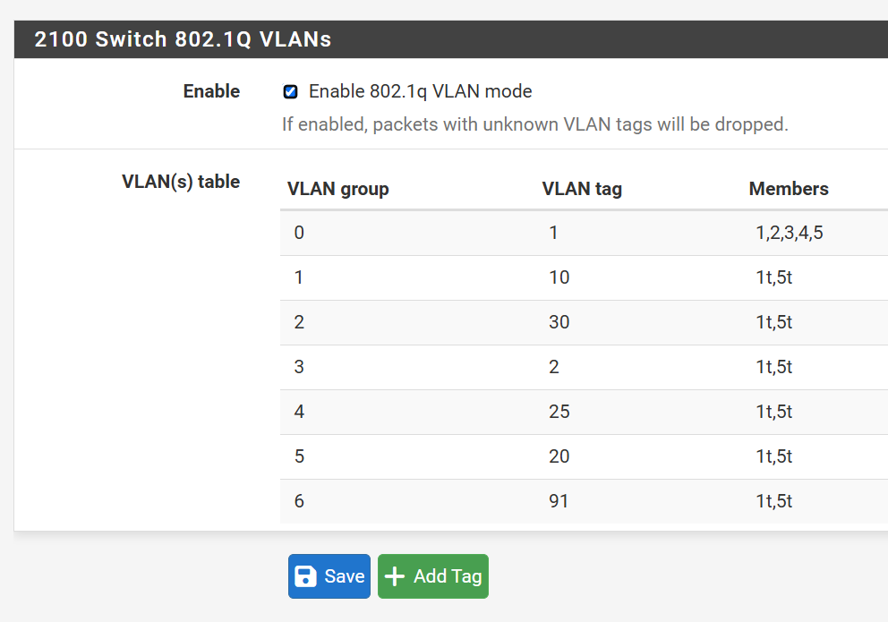
This image helps me visualise what is happening when VLANs are configured. Members map to the physical port numbers as follows.
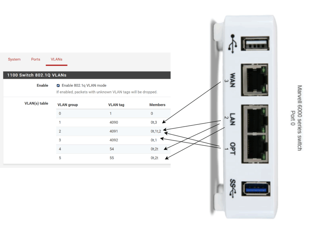
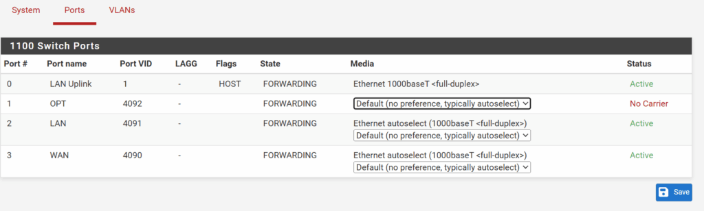
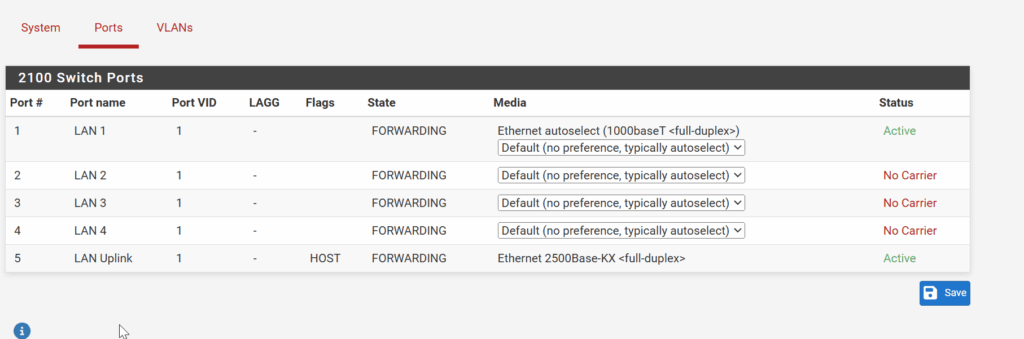
Switch Port numbers are listed under Interfaces / Switch / Ports
0 for the Marvell 6000 Switch Chip. Every VLAN other than 1 needs to have it as a tagged member (the 0t, xxx in the image above)
3 is the WAN port, 2 is the LAN port, 1 is the OPT port on the Netgate 1100
The members entries can be any of the above Port numbers (e.g. 0,1,2,3)
The t stands for tagged and is set when adding or editing a VLAN (i.e. traffic coming out the member port will be tagged with the appropriate VLAN ID when exiting the port). When you see a member without a t then that is the default or native VLAN so traffic on that VLAN will NOT be tagged as it exits the port (if I understand it correctly)
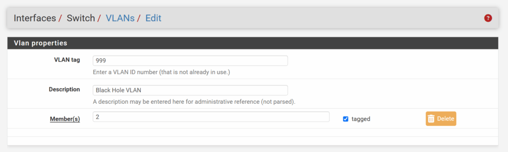
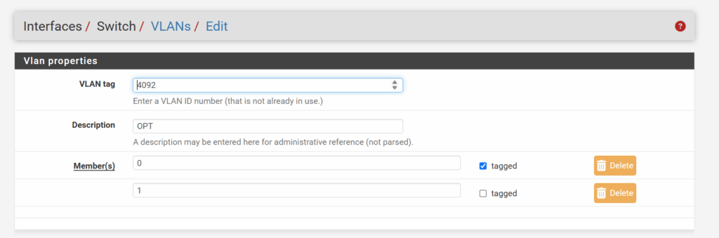
After you create your VLANs and add the member ports to each VLAN with appropriate tagged / non-tagged settings
You need to associate each VLAN with an Interface to enable routing
WAN (wan) -> mvneta0.4090 -> v4: 99.99.99.99/30
LAN (lan) -> mvneta0.4091 ->
OPT (opt1) -> mvneta0.4092 -> v4: 10.74.0.1/24
INT54 (opt2) -> mvneta0.54 -> v4: 10.18.54.254/24
INT55 (opt3) -> mvneta0.55 -> v4: 10.18.55.254/24
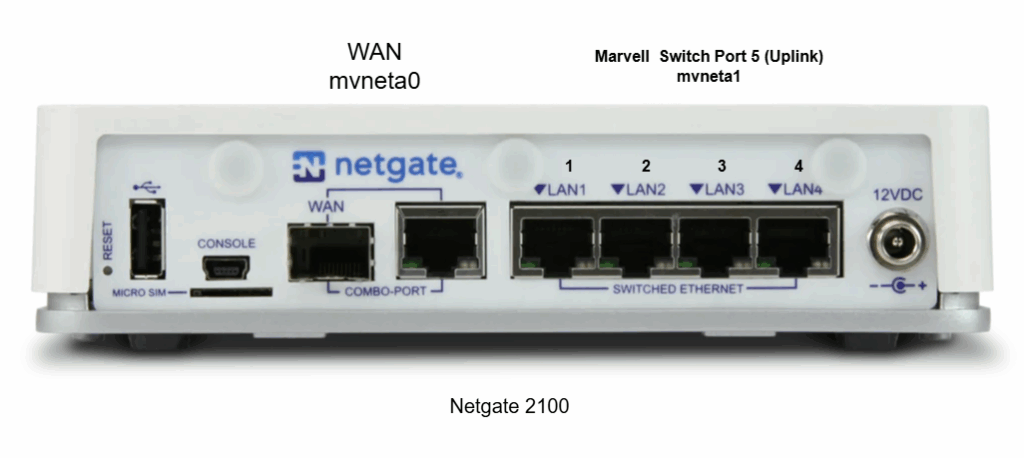
The Netgate 2100 uses the same Marvell Chip but different port assignments
The WAN port seems to be on a different device (mvneta0 with it's own MAC Address), and the 4 x ethernet ports are on the same Marvell Switch Chip and on (mvneta1 with it's own MAC Address)
0 Comments